Construction
Sep 9, 2026
The Unowned Scope: Attachment-Stack Coordination Failures Behind Modern Facade Defects
The Unowned Scope: Attachment-Stack Coordination Failures Behind Modern Facade Defects

The Unowned Scope: Attachment-Stack Coordination Failures Behind Modern Facade Defects
Modern facade defects rarely originate from a single defective component. More often, they form at the boundary between competent trades, approved submittals, and incomplete ownership.
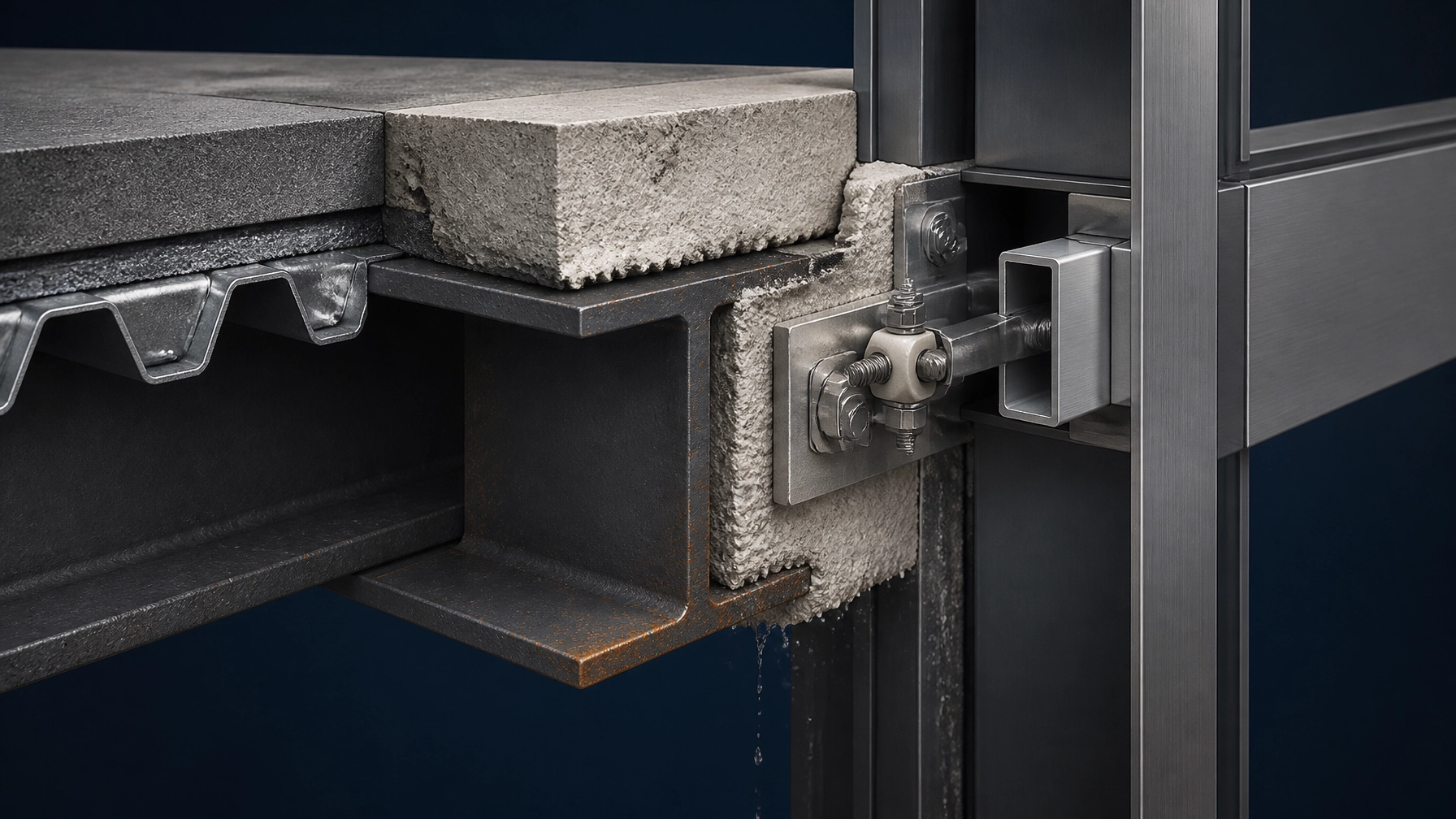
The interface between cementitious fireproofing and cladding attachments is a high-risk example. Structural steel, sprayed fire-resistive material, brackets, fasteners, rails, membranes, and facade panels may each be designed and installed under separate scopes. Yet the final performance of the assembly depends on how those scopes interact.
That interaction is frequently unowned.
In Dubai, Singapore, the UK, and other highly regulated construction markets, this gap can produce more than an untidy interface. It can create compromised fire-resistance continuity, concealed galvanic corrosion, water retention, disputed responsibility, and expensive remedial access after the facade is complete.
At exposed steel facade frames, cementitious fireproofing is often applied before the cladding support system is fully installed. The fireproofing contractor works to structural steel drawings. The facade contractor works to bracket and panel drawings. The steel fabricator works to connection details. The coatings contractor works to a corrosion-control specification.
Each party may be performing its contractual task correctly while the assembled interface remains defective.
Typical failure conditions include:
The visible symptom may be blistering, staining, corrosion bleed, cracking, debonding, panel movement, or a local gap in the fire protection layer. The originating failure, however, is usually contractual and procedural: no party was assigned ownership of the complete interface.
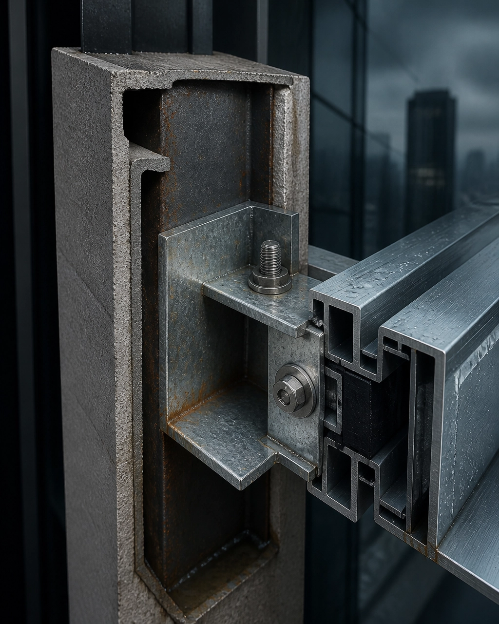
A forensic review should not begin with the assumption that the most visible component caused the defect. Reconstruct the complete attachment stack and identify every material, interface, sequence, and inspection hold point.
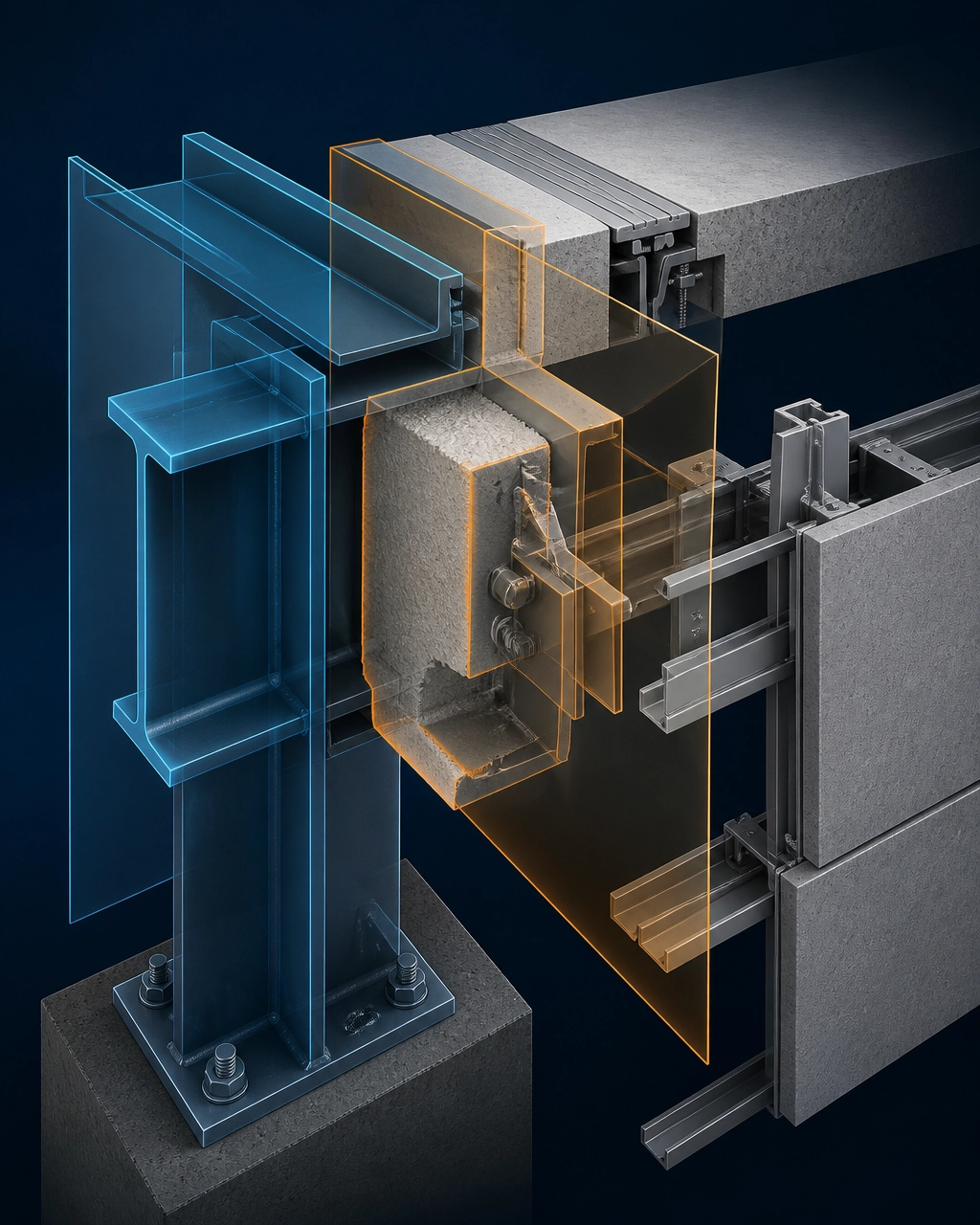
A typical assembly may include:
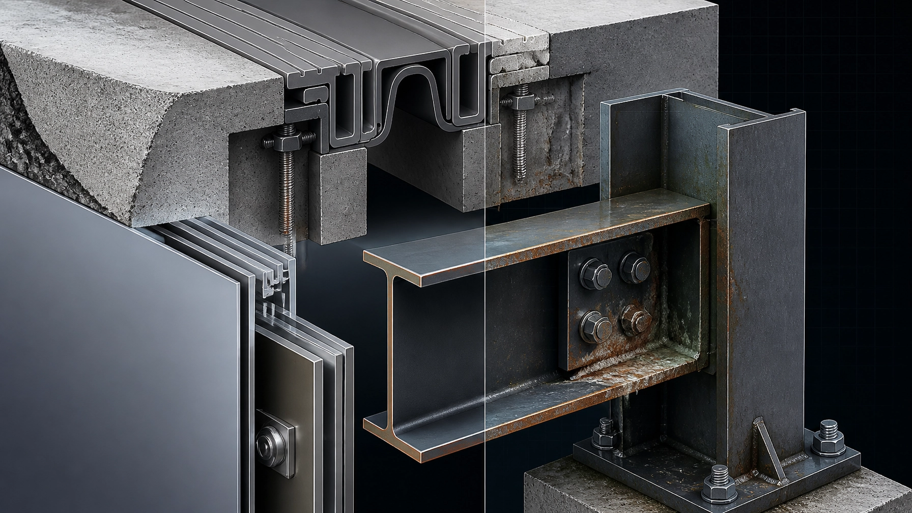
The risk is not limited to direct metal-to-metal contact. Moisture can create an electrolyte path between metals that are separated geometrically but connected electrically through fasteners, brackets, plates, or wet cementitious material.
Cementitious fireproofing is commonly treated as a uniform coating. At a facade attachment, it is not uniform. It has a termination, a return, an edge condition, and a relationship with the bracket plate.
Those conditions must be resolved before installation.
A field worker who cuts back material to achieve a clean bracket fit may improve the visible finish while reducing the tested or intended fire-resistance configuration. Conversely, a fireproofing applicator who covers a bracket without understanding its drainage, movement, or inspection requirements may create a water trap or obstruct future maintenance.
This is where the clash between “quality of finish” and structural or fire-performance requirements becomes material. A smooth, visually complete surface is not necessarily a compliant or durable interface. The correct question is not whether the finish looks continuous. It is whether the complete assembly retains its required performance after attachment, movement, moisture exposure, and maintenance access are considered.
Mixed-metal facade assemblies are particularly vulnerable where moisture is persistent and inspection access is limited.
A carbon-steel frame connected to galvanized brackets, stainless fasteners, and aluminum rails contains several different electrochemical materials. If moisture bridges these materials, the more anodic metal may corrode preferentially. The rate and severity depend on the alloy combination, surface condition, electrolyte, area ratio, temperature, and duration of wetness.
Cementitious fireproofing must not be assumed to prevent this process. It is a fire-resistive material, not a complete corrosion-control system. Its porous nature may also retain moisture when the surrounding facade detail does not drain or dry effectively.
Review the following forensic indicators:
The critical distinction is between material failure and interface failure. A bracket may be adequately designed in isolation. A fireproofing product may have passed its required testing. An aluminum rail may meet its coating requirements. The defect can still arise because the combined stack was never reviewed as one system.
The audit model often determines whether the defect is found early or discovered after enclosure.
End-stage audit:
The completed facade is inspected visually, usually after concealment. This model is efficient for documentation but weak at identifying hidden interface defects.
Trade-specific audit:
Each contractor verifies its own scope. This can confirm fireproofing thickness, bracket installation, or panel alignment, but it may not confirm the relationship between them.
Interface-led audit:
A coordinated review examines the complete attachment stack before concealment. It verifies drawings, materials, sequencing, isolation, drainage, fireproofing continuity, and inspection evidence. This is the most effective model for unowned scope conditions.
Use the third model where the consequence of concealed failure includes fire-performance uncertainty, corrosion, water ingress, or major facade removal.
No single standard resolves this interface. The standards must be assigned to the performance question they actually address.
Use ASTM E119 to establish the fire-resistance performance of the relevant building construction or structural assembly.
Use:
These references support performance verification. They do not automatically resolve the geometry of every facade bracket or confirm that the attachment interface remains equivalent to the tested condition.
Use ASTM G71 when galvanic corrosion testing in an electrolyte is required.
Use ASTM G82 to support the development and application of galvanic series information when assessing dissimilar metal combinations.
Use ISO 12944 to establish the broader framework for corrosion protection of steel structures through protective paint systems and exposure classification.
These references do not substitute for project-specific material compatibility review. They provide the technical basis for evaluating corrosion risk, coating durability, and environmental exposure.
Use relevant AAMA performance and coating references for aluminum facade components, including AAMA 2604 or AAMA 2605 where the specified finish requires those performance levels.
Use applicable SMACNA architectural sheet-metal guidance to review flashing, drainage, formed metal interfaces, and water management around attachment zones.
Do not treat these standards as separate silos. Link them through one coordinated interface register that records which standard governs each component and which party verifies the completed assembly.
Prevent the unowned scope gap by making the attachment stack an explicit deliverable.
Assign ownership for:
Name one coordinating authority. Do not assume that shared responsibility creates accountability.
The drawing should show the steel member, coating, fireproofing extent, bracket, fasteners, isolators, rails, membranes, sealants, drainage paths, and inspection zones.
Record:
Do not approve separate trade drawings without reviewing their composite condition.
Complete the coordination review before fireproofing application at facade attachment zones.
Then verify:
Where field modification is necessary, require documented technical approval before material is removed or reinstated.
A compliant fireproofing product does not prove a compliant facade interface. A corrosion-resistant fastener does not prove a corrosion-resistant attachment stack.
Test or assess the assembled risk where the project includes:
Maintain one coordinated record containing:
This evidence protects the project from an unstructured dispute in which each contractor demonstrates that its own scope was complete while the interface remains unexplained.
The unowned scope is not a minor coordination inconvenience. It is a latent defect mechanism.
At exposed steel facade frames, fireproofing, structural attachments, facade metals, coatings, membranes, and inspection regimes must be evaluated as one performance system. Assign the interface. Review the sequence. Isolate incompatible metals. Control moisture. Verify the concealed work before the facade removes access.
Shoal Bay Projects operates as the forensic advisory bridge between design intent, site execution, compliance interpretation, and defensible project records. The objective is not to allocate blame after failure. It is to prevent an interface defect from becoming a fire-performance uncertainty, a corrosion claim, or a legal and financial event.
For deeper construction intelligence, subscribe to the Shoal Bay Projects Hive YouTube channel.
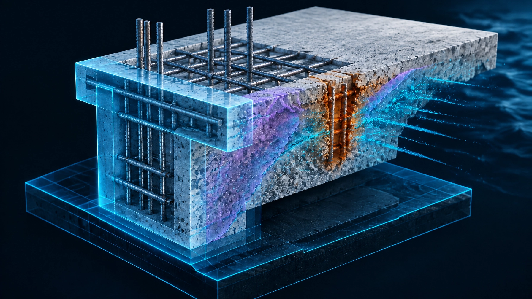
⚠️ The image in this post is used for illustration purposes only, designed to encourage thoughtful discussion. It is not intended to represent a prescriptive detail of any installation or construction method.
The Vault. The App. The Community. We're opening the doors to a select group of Foundation Members : free, for a limited time. Foundation Membership includes full access to The Vault (our forensic intelligence archive) and early access to the Hive app.
Once the charter window closes, this tier is gone permanently. Foundation Members retain access for life. This is not a trial : it's a permanent invitation to the founding cohort.
Claim Your Foundation Membership →
A new forensic intelligence brief for the community:
Facade defects often form in the space between scopes. This article examines what happens when cementitious fireproofing, exposed steel, mixed-metal brackets, fasteners, and cladding rails are each reviewed separately: but never as one attachment stack.
The Unowned Scope: Attachment-Stack Coordination Failures Behind Modern Facade Defects
Read the full article on Shoal Bay Projects: https://shoal-bay-projects.webflow.io
Explore more construction intelligence through the Hive YouTube channel.