Problem
Large-format glazing can appear complete, aligned and visually precise while its structural support conditions remain unverified.
The failure is often not a dramatic installation error. It is an assumption: that the opening is true, the sill is adequately supported, the anchors engage the intended substrate, and the frame can accommodate movement without transferring unintended stress to the glass. Those assumptions may pass unnoticed when the finished surface looks clean.
Large glass panels leave little margin for uncertain bearing, uneven support or uncontrolled frame movement. If a frame deflects, a support settles or the building moves, clearances and glazing engagement can change. The result may be edge contact, sealant distress, glass damage, water ingress or a dispute over which party was responsible for checking the condition.
The friction point is predictable. Contractors may regard appearance and installation completion as evidence of quality. Designers and oversight bodies may be concerned with structural performance, specified tolerances and documented verification. Neither view is sufficient on its own. A visually acceptable finish does not prove structural capacity; a technical requirement that was never translated into a field check may not be verifiable after the work is concealed.
For a medium- or high-end residential project, the cost of resolving that gap after completion can be substantial. A construction consultant or residential building consultant can help define what must be checked, when it must be checked and what evidence should be retained.
Forensic Analysis
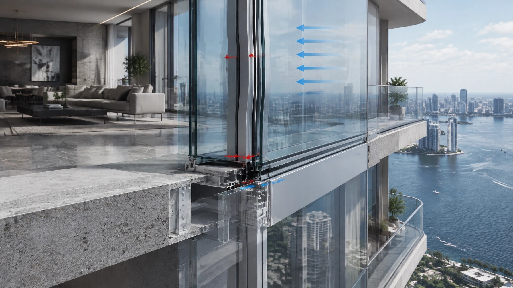
A large-format glazing system is not just glass in a frame. It is a connected assembly: glass, setting blocks, frame members, anchors, substrate, perimeter joints and adjacent structure. Its performance depends on how those parts transfer load and accommodate relative movement.
Start by separating the relevant movement sources. Wind pressure can deflect the framing. The glass and frame may respond differently to temperature change. Building movement, construction tolerances and local support conditions can alter clearances. If a design relies on structural sealant, joint dimensions, substrate preparation and curing conditions also affect the connection’s performance.
The critical question is not whether movement exists. It is whether the system has a defined and verified path to accommodate it.
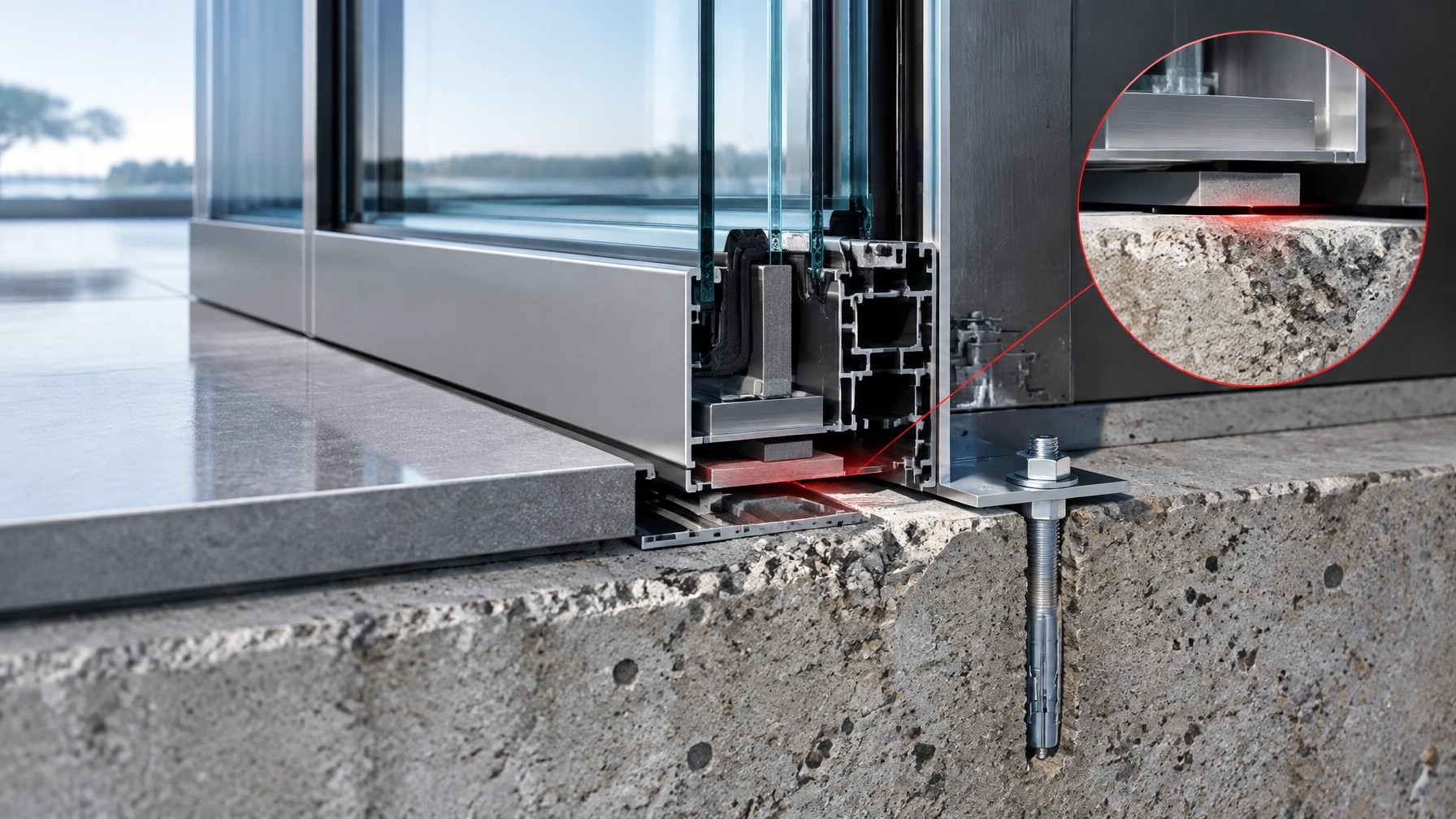
Check the design assumptions against the actual opening. Confirm the bearing locations, substrate condition, support continuity, anchor positions and available clearances. Compare the installed geometry with approved project documents. Do not assume that a frame can correct an out-of-tolerance opening, or that packing a visible gap resolves an unverified load-transfer condition.
Finish is not structural verification
A clean perimeter seal and consistent sightlines can create a strong impression of quality. They do not establish that the frame bears where intended, that anchors are adequately engaged, or that the assembly can accommodate the movement assumed in its design.
This is where construction compliance and site execution can diverge. A contractor may record completion based on the visible work. An oversight body may require evidence that concealed supports and connections match the design. If the project has no defined inspection hold point, photographs, measurements and records may not exist when a concern is raised.
The audit model matters, too. A one-off inspection late in the project can identify visible defects, but it may miss conditions already concealed. Conversely, an audit that is not clearly scoped can be mistaken for full approval of design, installation or regulatory compliance. Define the scope, timing, limitations and reporting pathway before inspection begins. Keep technical review distinct from the contractor’s installation responsibilities and the designer’s design obligations.
For construction risk management services to reduce, not merely document, risk, review must be timed to influence decisions. Inspect the opening and support conditions before glazing installation, when correction remains accessible. Record what was measured, what was compared and who accepted any deviation.
What the evidence should show
A defensible verification record should connect the design requirement to the field condition. Capture the opening’s dimensions and alignment; support and anchor locations; substrate condition; frame position; specified clearances; and any approved deviations. Photograph concealed components before they are covered. Identify the applicable drawing or calculation revision and record the person responsible for review.
If a test or mock-up is specified, define its purpose and acceptance criteria in advance. A test result is meaningful only in relation to the specimen, loading, measurement locations and stated performance limits. It does not automatically validate every installation condition on the building.
For clients searching for a “custom home build consultant Australia,” the same technical distinction applies globally: visible workmanship, designed performance and verified site conditions are separate questions. A building consultancy services provider can help connect those questions without replacing the roles of the project designer, contractor or independent testing body.
Standard Reference
Use standards as defined tools, not as substitutes for project-specific design or field verification.
- ASTM E330/E330M provides a test method for evaluating structural performance of the specified exterior window, door, skylight or curtain-wall specimen under uniform static air-pressure difference. Its scope is limited: it does not evaluate the structural adequacy of the glass itself or the adjacent construction. A successful test therefore cannot, by itself, verify the actual support conditions on every elevation.
- ASTM E2099-23 addresses specification and evaluation of pre-construction laboratory mock-ups of exterior wall systems. It emphasizes coordination among the specifier, builder and test agency, with time allowed for changes before full construction proceeds.
- ASTM E1105 provides a field method for assessing water penetration through installed exterior assemblies under specified conditions. It can help assess installed performance, but it does not replace structural support verification.
- ISO 28278-2:2010 addresses assembly rules for structural-sealant glazing, including project quality-control requirements.
Confirm the applicable editions, project specifications and jurisdictional requirements with the responsible design and compliance professionals. Do not treat a laboratory test, standard reference or manufacturer detail as automatic acceptance of an unverified site condition.

Actionable Fix
Set a pre-installation hold point. Survey and record opening dimensions, alignment, bearing locations, substrate condition and anchor positions before glazing work proceeds. Compare actual conditions with approved drawings and project tolerances.
Resolve deviations before covering them. Stop and refer unverified supports, altered anchors, damaged substrates or out-of-tolerance openings to the responsible designer. Obtain a documented disposition. Do not rely on improvised packing or sealant to correct a structural discrepancy.
Define movement and clearance checks. Confirm that the project documents identify relevant movement assumptions and required clearances. Check that the installed condition preserves the specified engagement and does not create unintended contact between glass and frame.
Use a representative mock-up where appropriate. Specify the test purpose, specimen details, measurement locations, loading sequence and acceptance criteria. Record changes made after testing and confirm that production installation reflects the accepted details.
Create installation records. Photograph concealed supports and anchors before they are covered. Record measurement results, material and component identification, deviations, repairs and approvals. Retain the records with the relevant drawing and calculation revisions.
Define audit scope and responsibility. State whether an inspection is visual, dimensional, documentary or performance-based. Identify what was not inspected and what remains the responsibility of the designer, contractor or test agency. Use staged review rather than relying solely on a late completion audit.
Escalate early. If evidence is incomplete or the installed condition differs from the design, seek a qualified technical review before finishes conceal the interface or a dispute fixes the parties’ positions.
Shoal Bay Projects operates as a forensic advisory bridge between site execution and technical requirements. Our building support, homeowner guidance and technical consulting help clarify construction compliance, review evidence and identify project risks while corrective options remain available.
Watch more construction intelligence on the Shoal Bay Projects Hive YouTube channel.
⚠️ The image in this post is used for illustration purposes only, designed to encourage thoughtful discussion. It is not intended to represent a prescriptive detail of any installation or construction method.
Claim Your Foundation Membership
The Vault. The App. The Community. We're opening the doors to a select group of Foundation Members. Free, for a limited time. Foundation Membership includes full access to The Vault (our forensic intelligence archive) and early access to the Hive app.
Once the charter window closes, this tier is gone permanently. Foundation Members retain access for life. This is not a trial: it's a permanent invitation to the founding cohort.
Claim Your Foundation Membership →
Circle-Ready Pack
A clean finish can conceal an unverified support condition. This article examines why large-format glazing needs more than visual sign-off, and how to make movement, bearing and audit responsibilities verifiable.
The Movement Assumption: Why Large-Format Glazing Systems Are Installed Without Verified Structural Support Conditions
Publication home: The Hive
- A laboratory test of a specified specimen does not verify every installed support or the adjacent structure.
- Check opening geometry, bearing, anchors and clearances before glazing conceals the condition.
- Define audit scope, hold points and evidence requirements before issues become disputes.
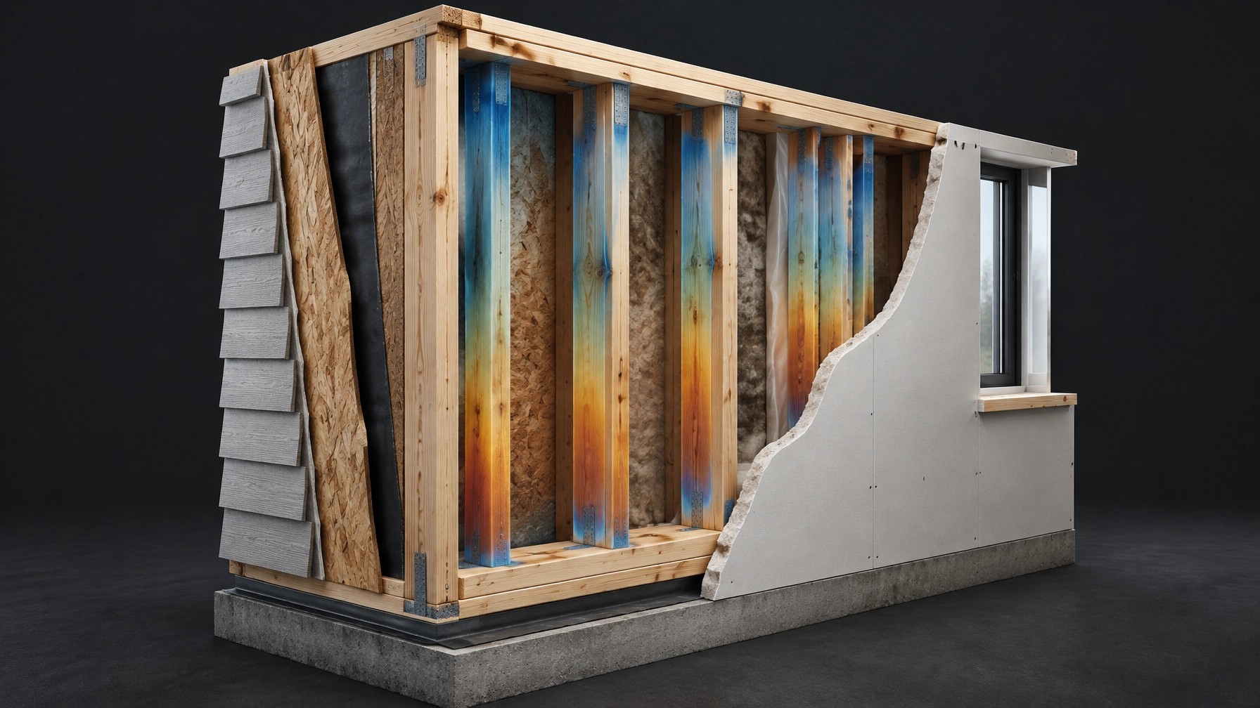
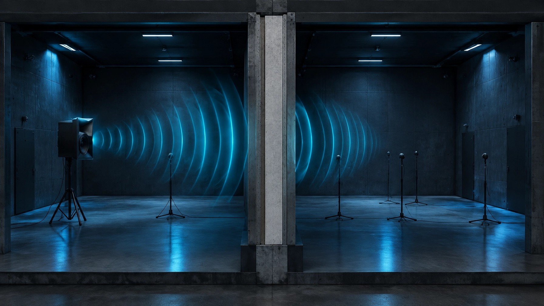
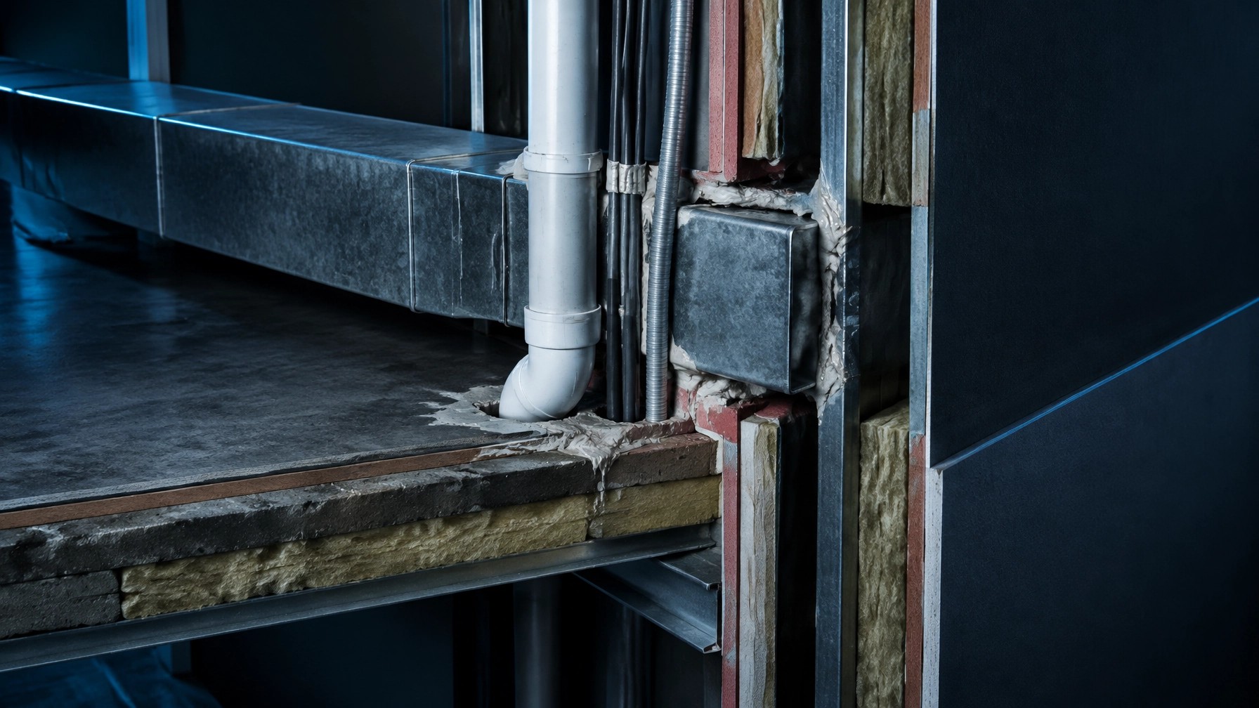
Image assets: Four original 3D forensic illustrations are included in the article: concealed support cutaway (https://cdn.marblism.com/O3wbiqc6fra.jpeg), discontinuous bearing section (https://cdn.prod.website-files.com/6a0c278cc2a032010f1c4626/6aebc719b4e133977527b819_h9I9S5hy_9C.jpeg), simulated movement visualization (https://cdn.prod.website-files.com/6a0c278cc2a032010f1c4626/6aebc719b4e133977527b7ff_qI0vRH-OLal.jpeg), and laser survey scene (https://cdn.prod.website-files.com/6a0c278cc2a032010f1c4626/6aebc719b4e133977527b816_1DJfHYCGII5.jpeg).