Construction
Jul 20, 2026
Precast Concrete Panel Joints: Why Sealant Depth-to-Width Ratio Errors Drive Failures
Precast Concrete Panel Joints: Why Sealant Depth-to-Width Ratio Errors Drive Failures

Precast Concrete Panel Joints: Why Sealant Depth-to-Width Ratio Errors Drive Failures
Joint failures at precast panel interfaces generate warranty disputes at a rate disproportionate to almost any other building envelope component. When longitudinal splits or adhesion failures appear, the default industry response is to blame the applicator. However, forensic investigation consistently reveals that the majority of these failures are not workmanship defects, but rather geometry failures rooted in the specification stage.
The disconnect between structural erection tolerances and sealant performance requirements creates a "tolerance stack" that effectively guarantees failure before the first caulk gun is even loaded. To mitigate six-figure remediation risks, building consultants and engineers must shift from a product-focused specification to a geometry-mandated advisory.
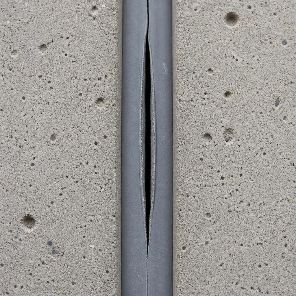
In high-performance facades, sealant is a structural component designed to accommodate cyclic movement. Its ability to perform depends entirely on its cross-sectional shape. When sealant fails, it typically presents in one of two modes: cohesive failure (tearing down the centerline) or adhesive failure (detaching from the substrate).
Forensic analysis of failed precast joints often reveals "inverted depth-to-width ratios." In these cases, the sealant bead is deeper than it is wide. This creates a cross-section that is too stiff to elongate. When the precast panels contract in cold weather, the sealant cannot stretch; the internal stresses exceed the material's cohesive strength, and it splits.
Conversely, when the sealant is too shallow relative to the width, it lacks sufficient mass to distribute stress, leading to premature failure at the adhesion plane. Neither of these is a product failure: they are geometry failures caused by a design gap.
The core of the issue lies in the delta between the "design joint width" and the "installed joint width." A typical architectural drawing might specify a 20mm (3/4") joint. However, precast erection is subject to a complex stack of tolerances:
When these factors accumulate, a designed 20mm joint can legally present to the installer as anything from 6mm (1/4") to 32mm (1-1/4").
A sealant specification that calls for a "standard 12mm (1/2") depth" fails at both ends of this spectrum. At the narrow 6mm end, a 12mm depth creates a 2:1 ratio: exactly the opposite of what physics requires. At the 32mm end, the 12mm depth is insufficient to distribute load. The failure is latent; it remains invisible during the initial inspection and only manifests after a full seasonal thermal cycle.
A common error in construction documentation is the over-reliance on ASTM C920 (the standard for sealant movement classification) while ignoring ASTM C1193 (the standard guide for joint geometry).
Specifying a "Class 50" sealant: capable of 50% movement: is irrelevant if the joint geometry is configured to fail. A high-performance sealant installed with an inverted ratio will fail faster than a lower-rated product installed with correct 1:2 geometry.
The backer rod is the primary tool for controlling this geometry. Yet, backer rod selection is routinely treated as a "field call" left to the installer. When the engineer abdicates the decision of backer rod diameter and depth-to-width ratios, they are essentially delegating the engineering of the building’s primary weather barrier to a sub-contractor with no access to the structural movement calculations.

To eliminate geometry-driven failures, the specification must transition from fixed dimensions to a variable matrix. A coordinated advisory approach involves three critical steps:
Include a table in the design documents that maps the installed joint width ranges to specific backer rod diameters and sealant depths. This removes decision-making from the field. For example:
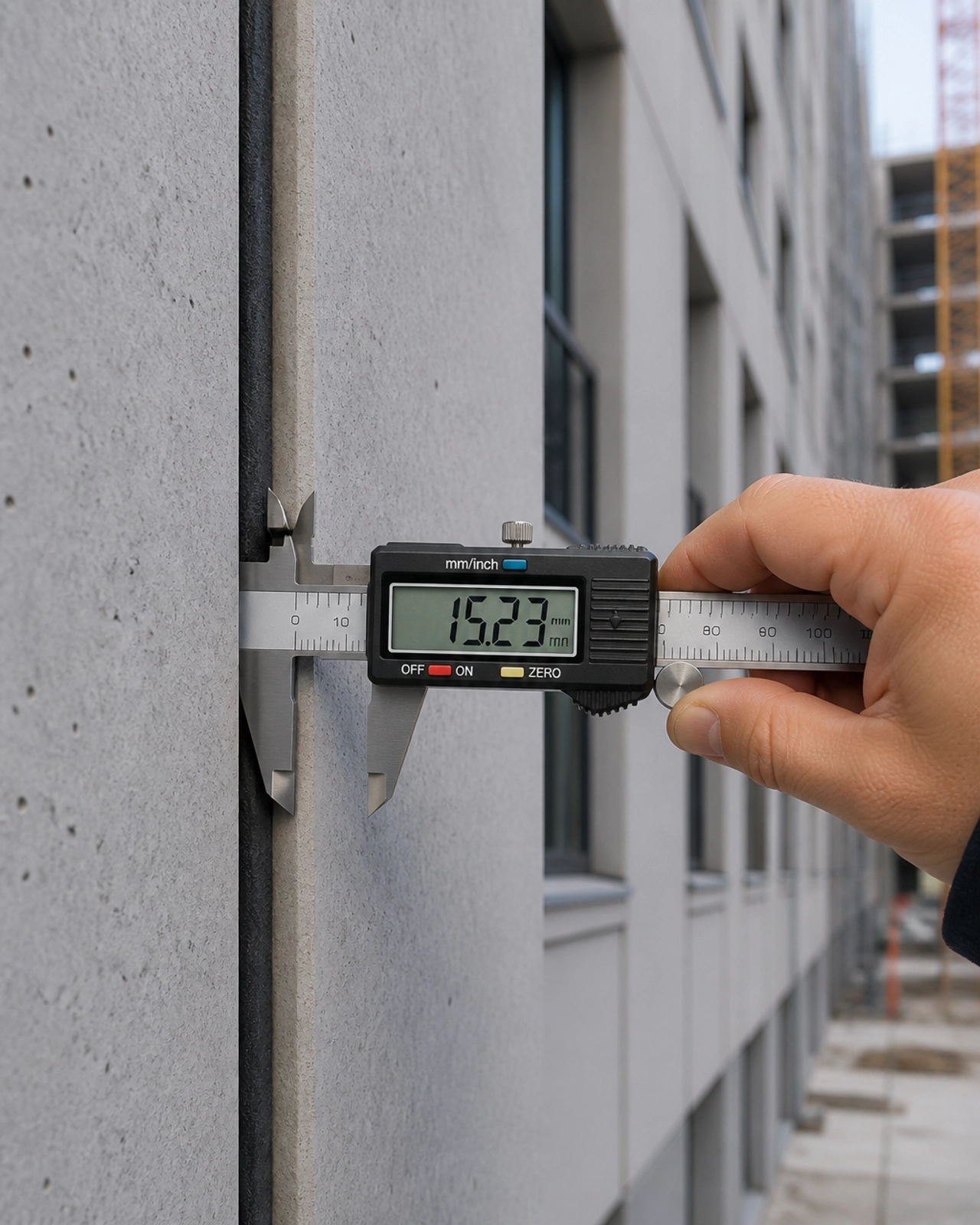
Specify a requirement for a joint width survey before any sealant work begins. A technician should measure the actual gaps on each elevation using digital calipers. If the survey reveals joints that fall outside the structural movement capability, the engineer of record must be notified before the joints are "sealed-in." This prevents the "covering up" of structural tolerance errors that eventually become six-figure warranty claims.
Ensure that envelope consultants review precast erection drawings before panels are cast. Most reviews focus solely on structural adequacy, missing the opportunity to adjust joint widths for thermal movement. Coordinated review ensures that the residual gaps left after erection are actually sealable.
The sealant joint is the most worked component of the building facade. Treating it as a finishing trade rather than an engineered assembly is a high-risk strategy. By owning the depth-to-width ratio as a design decision and mandating field surveys, developers and builders can bridge the gap between structural reality and envelope performance.
The Vault. The App. The Community. We're opening the doors to a select group of Foundation Members — free, for a limited time. Foundation Membership includes full access to The Vault (our forensic intelligence archive) and early access to the Hive app.
Once the charter window closes, this tier is gone permanently. Foundation Members retain access for life. This is not a trial — it's a permanent invitation to the founding cohort.
[Claim Your Foundation Membership →]
Circle-Ready Summary
Precast panel joint failures are rarely about the "caulk": they are about the "gap." In our latest deep dive, we analyze why the depth-to-width ratio is the most common failure point in modern facades and how "tolerance stack" makes standard specifications useless.
Key Takeaways:
Read the full forensic analysis here: Precast Concrete Panel Joints: Why Sealant Depth-to-Width Ratio Errors Drive Failures
Foundation Member CTA:
[Claim Your Foundation Membership →]
⚠️ The image in this post is used for illustration purposes only, designed to encourage thoughtful discussion. It is not intended to represent a prescriptive detail of any installation or construction method.